Well I I finaly have it finished and I bench tested it to make sure it is in working condition. It is running fine! I even hooked up a spare 4-2 CAS on a drill to make sure that everything was working OK.
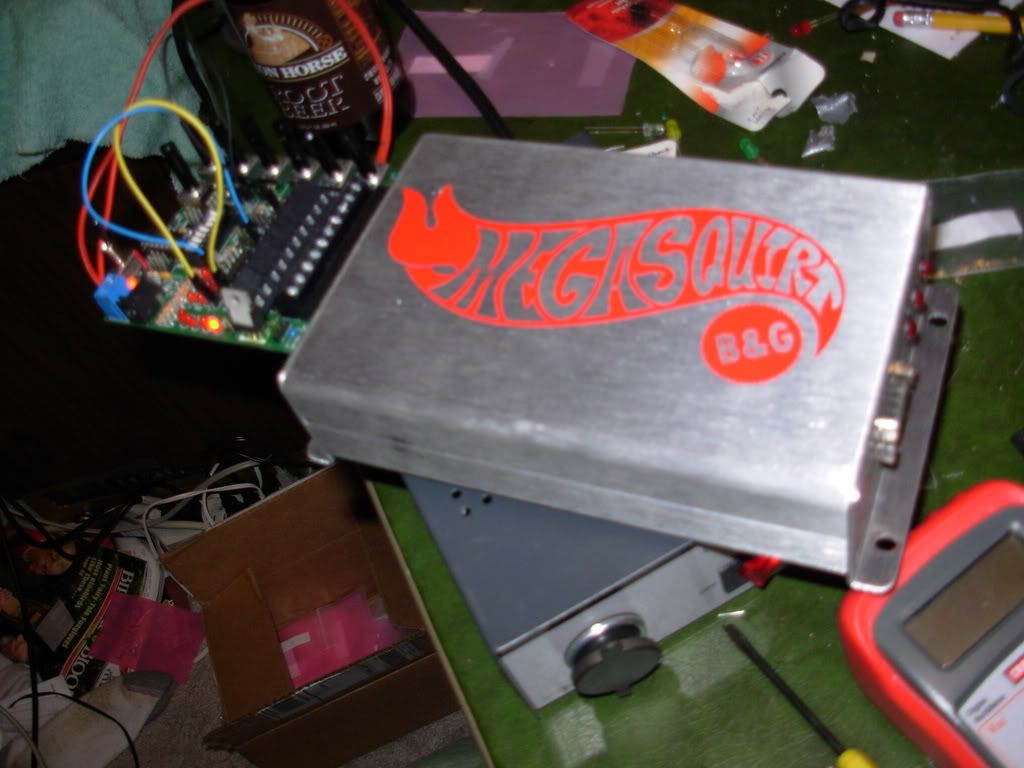
The box is the ECU itself
The circuit board is the tester that I can control simulations like RPM, Coolent temp, TPS, O2, MAT
When the weather warms up a bit, it will be installed into the car.
I am still thinking of how I want to install it however.
There are two ways,
I can use this as a fuel controler, or I can use this for both fuel and spark.
If I hook it up just using fuel I would have to splice into the harness for all the signals. I would however have the ability to just run fuel and not have to worry about tuning the spark for right now.
The other route is just take control of fuel and spark. That way all I would have to do is remove the stock ECU and just hook up to the existing harness. No splicing. This also means that I won't have to deal with a MAS or what I am running right now a MAFT
Here it is in action:
http://s217.photobucket.com/albums/c...t=DSCN1830.flv
The lights are alternating with the flashing in real life. I think the cameras resolution didn't quite capture it well enough. On the board the lights on top are the injector banks firing and on the front cover and on the other lights on the test board are the spark outputs
This is sweet as hell. All it started out was with little resistors, diodes, chips and other stuff. All soldered together and it is alive! Kind of like rebuilding your first engine, you never would think that it would run and suprised when it does...
